 So the parts I ordered finally came in and I was able to put a solid six-hour day in at Techgarage building Slidemap V10 based off of my CAD. When I initially designed this version I intended for it to be a solid machine with rigidity and enough power to support high loads. While this is usually a goal that you set when trying to build a CNC router for a slide scanner that requires very precise movement of very light objects it isn’t necessary.
Pros of V10
- Rigid
- Accurate Movement
Yep, that’s it and while these things are important they don’t take precedence over other features such as vibration mitigation. These pros also certainly do not outweigh the cons.
Cons of V10
- Heavy
- Expensive
- Minimized potential movement
- Limited screw access making maintenance harder
- Long build time
- Limited modularity
- Small maximum attachment size
So while I was able to create a solid compact machine the actual use cases for it is very limited and this could potentially hold me back in the future.
V10.1
So as quickly as I built it I had dismissed the idea of it potentially being the next linear motion platform I will use. When I got home I began cadding up a new design of Slidemap with a few main design goals.
- Lightweight
- Extremely Modular
- Inexpensive
And it turns out that lightweight and inexpensive are pretty much mutual. For example, on V10 I used 12mm inner diameter linear bearings along with 12mm rods. While these bearings are technically optimal for a high load application such as moving a block of steel in a CNC. For my application which is moving a microscope which is extremely light this bearing and rod combination just doesn’t make much sense. Thus, in the new design, I opted for much lighter 8mm linear bearings. I found a few of these lying around techgarage and was able to test them before ordering and I found that they also seemed to have much smoother motion than the 8mm linear bearings. This will reduce the load on the stepper motors and increase their overall lifespan.
As far as modularity is concerned I tried to design each axis separately. So rather than design the device as one complete system wehre, every axis relies on each other for support. Designing every axis separately allows them to be mounted in whatever orientation is optimal.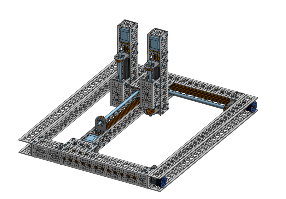
Slidemap Control
Now for controlling the stepper motors on Slidemap, I am going to use the Ramps v1.4 board combined with the Marlin firmware.
Ramps Board
The ramps board is a solution for controlling up to five steppers motors plus two extruder stepper motors for the Arduino.
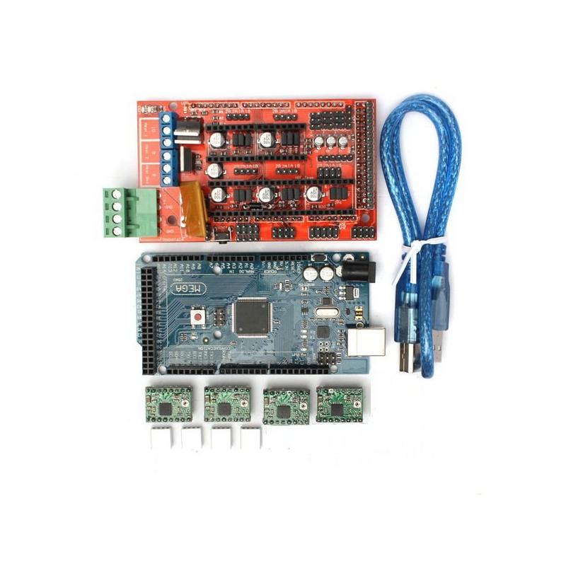
The actual board is in red and it is basically an Arduino hat that just sits on top of the Arduino. The cable on the right is used for flashing the Arduino mega with the proper firmware to control the board. The four green boards in the bottom are the actual stepper motor driver boards. Stepper motors require very precise timing in order to work properly. 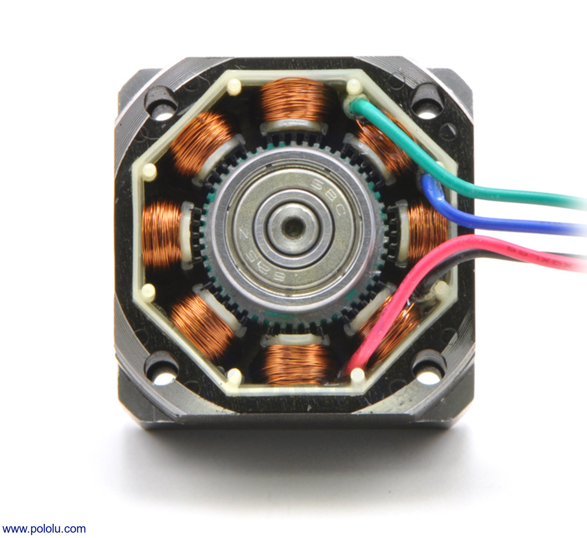 For a typical four-phase stepper motor there are multiple coils that can be turned on in two distinct groups. By energizing the coils at the right time and turning them off at the right time you can make the axle of the stepper motor move one step. In this case, one step is one of those little grooves that surround the axle. This allows for a very high torque output with very small movement which is what makes stepper motors unique and perfect for this kind of application. This Ramps board also communicates using G-code. So G-code is a communication standard for all sorts of machines from CNC machines to laser cutters. Due to this variety, there are hundreds of commands that you can send to do varies things on the machine. For example, G0 is for sending a single axis to a certain mm position. G0 Y10 would send the Y-axis to 10mm. They have other commands such as G02 which move the entire machine in an arc pattern. This is what the Marlin firmware does.
Marlin Firmware
The Marlin firmware is a G code reader. It can be flashed to an Arduino and if you connect to the Arduino over USB from a computer you can send the G-Code commands as strings and they will be interpreted by the marlin firmware on the Arduino and then it will control the ramps board to move certain stepper motors to complete the sent command.
Slidemap Resolution
Slidemap needs the ability to move at cellular precision in order to capture pictures of an entire microscope slide. This brings up the question, are stepper motors accurate enough? In fact, they are!
A typical stepper motor has about 200 steps per revolution
The lead screw I am using moves the axis 8mm per revolution
This means that every 8mm there are about 200 steps, so dividing 8mm/200steps we get 40um per step. Assuming a typical human cell is about 10um we would move about 4 cells per step and there are about 10 cells per image. This means we have more than enough resolution and this doesn’t even take into account microstepping and the potential of using 400 steps per revolution stepper motors. Using 1/2 steps instead of full steps and using a higher resolution stepper motor we can get 10um per step! Even then if this isn’t enough resolution (which it should be) I can get stepper motors with gearboxes to reduce the movement per step even more.
Conclusion
While V10 didn’t go so well I can’t wait for the parts for V10.1 to come in because I really think this will be the one to get Slidemap working. Stay tuned!
