We are currently working on developing a 12ft scissor lift design using GoBilda for use on a warehouse automation robot we are working on. The scissor lift is capable of 12ft at full extension and uses consists of 4 stages of 43.5in cross members to achieve this. We started yesterday and this is what we have so far.

In this case we attached our 12inch stroke actuator to the bottom outside cross member and the other end to the second inside cross member. This had a few issues.
- Angle of attack when folded was extremely low
- Mounting solution cause binding at tall heights
- GoBilda channels would rather bend in this configuration instead of rotate
The lift as a whole somewhat worked with some initial assistance but is no were near ready to be put on a robot. I went back to the drawing board and did some experimentation in CAD with a couple designs. My main focus was to copy an existing heavy duty scissor lift that has a high actuator angle of attack at rest.
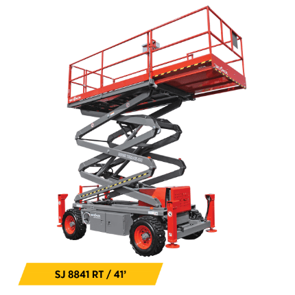
I decided on this lift which mounts to the first inside cross member then skips one and mounts to the third inside cross member. The reason I think this design will perform better is that the angle of attack at rest is much higher since a cross member is skipped giving it a greater angle. Its angle also adjusts as the scissor lift moves potentially providing a more consistent vertical force. The length of the actuator is also adjustable meaning we can move it down or up either cross beam to allow it to work with our chosen linear actuator.
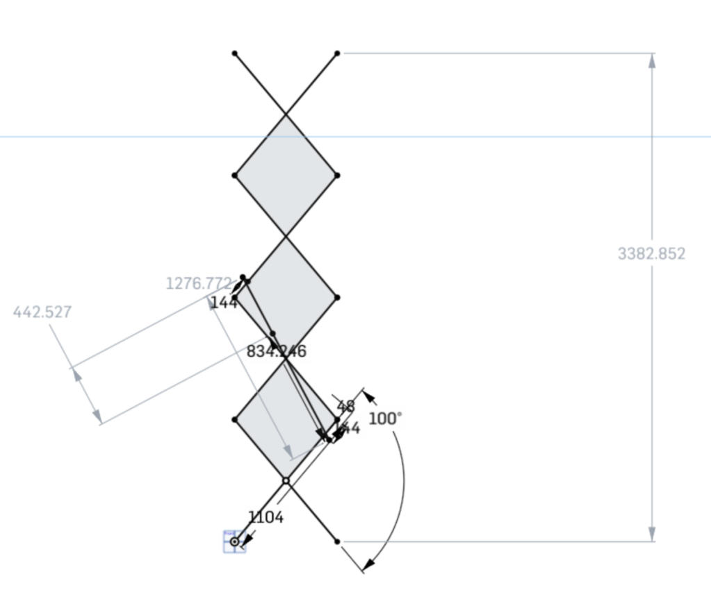
This is my representation of this design using my desired sizes in an Onshape sketch. The actuator pictured can be found here and is mounted 144mm from the outside joint on either cross member which lines up with the gobilda hole pattern. I also extended the mount point above and below to help increase the attack angle even more. When retracted the chosen actuator is 32.8in or 833mm which is just a little smaller then the actuator in this design so we shouldn’t have any conflicts here. Due to the positioning of the linear actuator on the cross members after 100 degrees of rotation the actuator reaches its max retracted length of 18in. Theoretically this doesn’t matter though since 100 degrees is more than enough rotation and anymore we would begin to sacrifice stability of the lift. This allows us to reach 11ft with four stages which of course can always add more. We also will have an additional foot of vertical space taken by the sum of the drive train the rail mounting system for the top and bottom of the lift and any attachments on top so we should have no problem reach our 12ft goal.
