I’ve been holding off on this project for about a month now, not because I don’t want to do it but because I know its a lot of work and as soon as I sit down to work on it I won’t be able to stop for days on end. Today I finally pulled the trigger and started the process of writing firmware from scratch for an advanced custom motor controller board. I have had a few other posts about this board in the past and writing firmware for it as well as an API however that was version one. Version two of the Brooklyn father card and the Empire daughter cards were just finished developing by my friend Kirill Safin. He shipped me some samples so that I can start writing firmware for them.
I had a few main goals for version two of this board.
- Needs to support two-way SPI communication from slave to master to allow for encoder values of each motor to be returned to the API.
- The father card should be able to flash the daughter cards instead of having to use a dedicated flashing card that only does one at a time.
- The code needs to be written very well and needs to have good documentation in order to make it easier to start adding advanced features such as PID control
The first thing I wanted to do was get out of using the Arduino IDE. While it is a great IDE for programming Arduinos with simple projects and makes it’s very easy to flash hex code and compile C++ code it just doesn’t have all the other tools of a modern IDE. In most of my other workflows, I use Visual Studio Code and think it is one of the most powerful and useful IDEs out there due to its simple design and its plugin market. VSCode is a very powerful editor in its own right but it is also fully open-source allowing independent developers to create powerful plugins that allow it to do even cooler things. Take a look at the marketplace here and see the wide range of things they can enable VSCode to do. It just so happens Microsoft (the creators of VSCode) have developed and published a plugin that allows VSCode to mimic the ease at which the Arduino IDE flashes Arduino microcontrollers.
When you first open VSCode you’re going to want to go to the left toolbar side and click the button that says extensions or press Ctrl+Shift+X to bring up the marketplace. Once here you just type in Arduino. 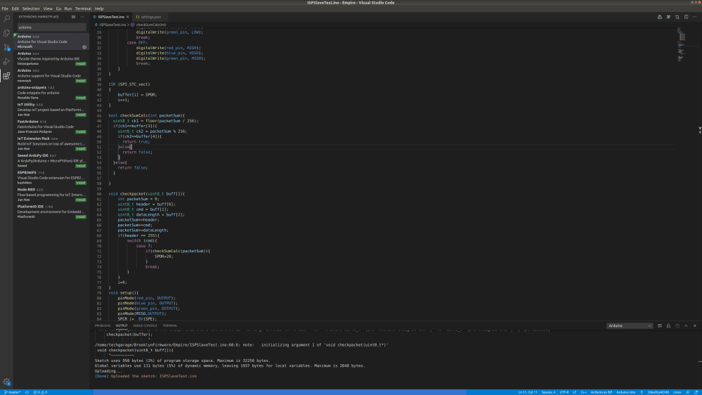
Then just click the first extension and hit install in the main windows. It will then install the extension for your use in all VSCode projects. Keep in mind this Arduino plugin will be enabled across ALL VSCode projects. In my experience, it has not interfered with any of my other extensions or my ability to run python code, etc but if you run into problems with other projects after installing this you can always go back to this extension and hit the disable button.
Now, this extension allows you to select things like your baud rate, board, COM port, programmer type, etc virtually all the settings present in the Arduino IDE. All this information is stored in two files that are created in whichever folder you opened with VSCode. When you open a folder it creates a .vscode folder that contains arduino.json and c_cpp_properties.json as you can see below.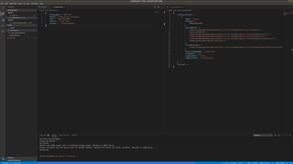
Now the arduino.json file will vary depending on what board your flashing, the name of your script, your COM port, and your programmer type but you can see the settings I used above. On the right is the c_cpp_properties.json file which basically helps Intellisense know where to find all the C header files typically present in the Arduino IDE. For example, when you use the command #include <SPI.h> you are basically importing the SPI.h file which wraps all the SPI communication in order to make it easy to program. This SPI.h file is present in the Arduino IDEs program files and this is how the IDE knows the file actually exists and your import is valid. Without knowledge of where the header file is the IDE would throw and error and your file would not be able to compile. The default c_cpp_properties.json file tries to include the necessary header files but I found it is missing a whole section of the IDEs header files and had to do a slight workaround. It kept warning me that the SPI.h file did not exist so I found the path in the Arduino IDE by just doing a quick search and found it is in nested folders under [Arduino folder location]/arduino-1.8.12-linux64/arduino-1.8.12/hardware/arduino/avr/. This was not previously present in this file which is why the IDE couldn’t do the header file. In order to add this, I added the absolute path to the include path variable in this son file with the same format the other paths were written then I added a double asterisk after avr/. VSCode will interpret this as me telling it to recursively search through all subfolders under the avr folder in order to find the SPI.h header file. Theoretically I could just recursively search through the arduino-1.8.12-linux64/ folder but this could cause performance loss as it tries to actually find the header file so I chose to do this instead.
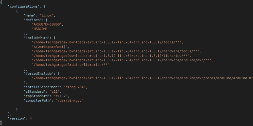
You will also notice that my defines section looks a little bit different than the default. TBH I have no idea what the ARDUINO=10800 does but I saw it on some website and added it when I was having problems. Anyways… what is important is the USBCON under the defines section. Without this, you will get errors when you try to use the Serial variable to print or read the serial console. The program will still compile but you will not be able to use IntelliSense for auto-complete without this and most importantly you will have the ugly red lines under every Serial you use which makes me want to vomit.
The last thing I did to fully setup VSCode for Arduino development was in the arduino.json file. I went ahead and added the line “output”: “./ArduinoOutput”. This will go ahead and cache the compiled hex file and other important information for uploading the code in a folder called ArduinoOutput. This allows the code compilation and uploading to be faster for very large files as the entire thing doesn’t need to get compiled just the things that change. This isn’t really necessary so if you don’t feel like it doesn’t add it but honestly, I like having all the features that are offered in this extension. Don’t worry about the rest of this we will set these in the next step using the nice UI they have put together.

If you look in the bottom right of your screen you will see a few buttons that got added as a result of installing the Arduino extension. Click on these will allow you to change the upload settings for your board. When you click select programmers you will be met with a bunch of options for just flashing a board connected to the computer over USB you can usually just use AVR ISP as a default. For the board type here you will obviously just select whatever board you are trying to program from the dropdown. The little plug looking thing opens up the serial port (I think) I usually just press F1 and type serial port in to open it but I don’t know this might work too. Then select the serial port that says Arduino LLC next to it when you hit the select serial port button. By doing all this it will automatically populate the arduino.json file with all these values. This is where you can go to change them across your projects.
Anything custom that you added to the arduino.json or c_cpp_porperites.json file will need to be added or copied to every Arduino file’s folder. There may be a way to do it automatically but I haven’t looked into it. Also one of the most annoying things I found about the Arduino IDE was that every .ino file has to have its own parent folder luckily for us when using VSCode it changes absolutely nothing… Every .ino still needs to have its own parent folder you cant have two .ino files per folder. The main reason for this is the way the compiler interprets multiple files per folder and actually compiles them. For example, if you have two different .ino files in the same folder each with a single void loop. The compiler will complain that two void loops are declared and will not be able to compile your main file. So uhh yeah you just kind of have to deal with the annoying folder file structure but that’s okay at least you get the benefits of VSCode to autocomplete, debugging, and IntelliSense which in my book is a massive win over the Arduino IDE.
Actual Code…
Alright, now that VSCode is FINALLY set up you can skip this if you just randomly found this blog post trying to get Arduino working in VSCode. But for all the nerd that is here to learn about code stuff and setting up SPI for two Arduinos as slave and master keep reading. Or just go to my GitHub page if you’re that lazy. Now on with the show.
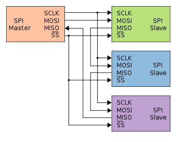
SPI communication or Serial Peripheral Interface communication is a type of synchronous communication that allows two devices to communicate at the speed of light. Well not the speed of light but pretty fast for two-wire communication 10Mbps. This protocol is typically used for high-speed communication with things like sensors hence the word peripheral. It operates using four pins and a master device. The master has the SCLK pin, MOSI pin, MISO pin, and the SS pin (there may be many SS pins more on that later). The SCLK pin is the clock pin which pulses high every time data is sent from the master. This allows the slaves to know exactly when the data is going to arrive which removes the issues associated with asynchronous communication like UART over USB that requires both devices to have the same baud rate. The MOSI pin stands for master out slave in when is the pin where the master device sends serial data on. It sends this data in sync with the clock pin so when the slave receives the data it knows exactly when to read the MOSI pin to read the correct bit. The MISO pin is master in slave out this is the pin that the slave devices write to when responding to the master. They also do this in sync with the clock and MOSI pins. This means slaves can only respond at the same time as data being sent to them. This means if the master sends something that requires processing and doesn’t have an immediate response. Another empty byte needs to be sent from the master to give the slave a chance to respond. Finally, the SS pin is specific to every slave. So if you have three slaves connected to the same master there will be three different SS pins one for each slave on the master. When information is being sent from MOSI the SS pin connected to the intended slave is set to LOW. This tells the slave that the data is intended for it and no other slaves. This allows you to have networks of devices all sharing the same three wires which makes SPI a cost-effective method of serial communication.
Now Arduino tries to make SPi very easy and Nick Gammon has many posts on various SPI techniques and more details on how it works so go check that out as well if you want to learn more. But what I have found in all the online “tutorials” for SPI communication on Arduino is that they are for very small projects with very low bandwidth. For example, sending information to the slave to do a single process than sending it back then the program is over. This really doesn’t represent the real-world application of SPI as a serial communication protocol. Typically serial communication is handled in terms of packets of data or packets of bytes. These bytes are sent in order typically header, command, data length, data, checksum 1, and checksum 2. This packet structure can vary across device but this is the most basic and what I will be using in this tutorial and throughout my project development. I simply couldn’t find anyone talking about how to send full packets at a fast speed back and forth using an SPI interface. So uh that’s what I’m going to try to do and try to explain (don’t worry the code is dumb easy). Also fair warning this isn’t the end of the tutorial but I do explain how to get basic SPI communication working. I should have the second half done tomorrow where I can send and receive full packets of data.
In order to get basic SPI communication, you need code for the master Arduino and the slave Arduino. The code I used on the Brooklyn board which is the SPI master is as follows.
#include <SPI.h>
#define SS A1

void setup(){
    Serial.begin(9600);
    pinMode(SS, OUTPUT);
    digitalWrite(SS, HIGH);
    SPI.begin();
}

void loop(void){
   digitalWrite(SS, LOW);
   SPI.transfer(78);
   delayMicroseconds(200);
   uint8_t resp = SPI.transfer(0);
   digitalWrite(SS, HIGH);
   Serial.print(resp);
}
The above code is the barebones for SPI master communication. We are importing the SPI class which is what makes this code so easy. We then define the SS variable or slave select pin as A1 which is connected to the SS pin on Arduino slave. For wiring diagrams find some other tutorial there are so many. In the setup, we are starting up the Serial interface to communicate back slave responses to the development computer. We set the salve select pin to output mode and write it high to ensure it is not trying to read noise on the SPI lines. We then begin the SPI interface no idea what this command doe shut everyone has it so uhh yeah just throw it in there it’s probably important. Then in the loop, we are making SS low so the slave begins to listen then we transfer the value 78 in bytes. it then waits for 200 microseconds to give the slave time to receive it and then we send an empty zero byte to allow the slave to send back its response to the 78. Then we write the SS pin to high to stop communication. Finally, we write a response to the serial console. Slave code is a little more involved but still extremely easy.
#include <SPI.h>
volatile uint8_t val;
ISR (SPI_STC_vect)
{
    val = SPDR;
    SPDR = 20;
}

void setup(){
    pinMode(MISO,OUTPUT);
    SPCR |= _BV(SPE);
    SPI.attachInterrupt();
}

void loop(void){
}
This code is designed for SPI devices where you don’t have access to the serial port such as the Empire daughter cards. These cards use embedded Arduino which doesn’t have access to the serial pins meaning I have no idea what is happening in the loop and the only way I can know what’s happening is by sending data back to the Brooklyn board for debugging. Anyways we go ahead and import SPI.h again. Then we define a volatile uint8_t this is because SPI on the slave side operates on interrupt so the main code will get interrupted and got to the ISR function where this variable is changed. Volatile is just indicating to the compiler that this variable will be changing a lot and at odd times. This ISR function has some weird format for who knows why but this is the only way it works so. Val is set equal to SPDR which is the value that was just sent on the MOSI pin. Then SPDR is set equal to 20 which will be sent on the MISO pin the next time the master sends data which in this case is an empty byte. The setup sets the MISO pin mode to output so we can actually write to it. Then the next two lines of code do some SPI stuff I don’t understand but allow it to work. And that’s it this will just respond 20 to whatever the master sends every time.
The only way to communicate with the Empire controller board is via SPI with the Brooklyn board. This means that’s also the only way to flash the Empire board. Luckily Arduino has provided an SPI programmer that allows you to program Arduinos using the only SPI instead of serial. So I modified the Arduino ISP file to have A2 as the reset pin and flashed it to the Brooklyn board which uses an Arduino Leonardo. I then changed the programmer from AVR ISP to Arduino ISP for the slave code and the board from the Arduino Leonardo to the Arduino Uno because the Empire boards use an Atmega328p. I then pressed F1 and hit upload using programming in VSCode which uploaded the entire file through the SPI interface. I then uploaded the master SPI code to the Brooklyn board overwriting the Arduino ISP code which then started running and I opened the serial monitor and saw a beautiful stream of 20 coming in.
Now that I have verified I can communicate using SPI one byte at a time I need to write a master code that allows you to send packets of data with one command acting as a middle man diverting day from the computer to the intended Empire controller. I also need to write code on the slave side that waits for data to come in and actually reads it in packet format and can properly determine what the command is then responded to the last byte sent from the computer which will be the second checksum.
Edits–
I found after burning the bootloader to the master Arduino that the SPI code no longer worked. I struggled with this problem for a couple hours then tried flashing everything using the Arduino IDE. The code worked immediately after doing this. So if you end up burning the bootloader should flash a couple programs using the Arduino IDE to configure the Arduino properly.

2 thoughts on “Brooklyn Board: Arduino ISP Testing”